Logic Gates
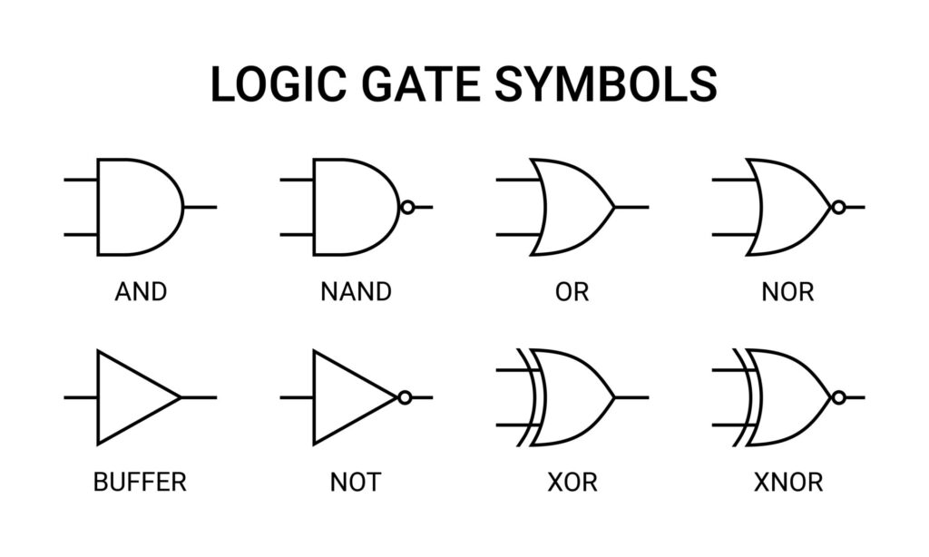
Transistors allow for the creation of logic gates, which physically represent Boolean logic. These gates serve as the physical, electrical realizations of Boolean functions.
A logic gate takes one or more input bits (0 or 1) and instantly produces an output bit according to a fixed rule (AND, OR, NOT, XOR, etc.).
Logic gates allow for the creation of complex structures, capable of adding, subtracting, multiplying, and storing digital information.
Buffer Gate
A Buffer gate passes input directly to the output without changing it.
| A | Output |
| 0 | 0 |
| 1 | 1 |
NOT Gate (Inverter)
A NOT gate is the opposite of a buffer gate and reverses the input. A high input becomes low, and vice versa.
| A | Output |
| 0 | 1 |
| 1 | 0 |
AND Gate
An AND gate produces a high output (1) only if all inputs are high (1).
| A | B | Output |
| 0 | 0 | 0 |
| 0 | 1 | 0 |
| 1 | 0 | 0 |
| 1 | 1 | 1 |
NAND Gate
A NAND gate is the opposite of an AND gate. It produces a low output (0) only if all inputs are high (1).
| A | B | Output |
| 0 | 0 | 1 |
| 0 | 1 | 1 |
| 1 | 0 | 1 |
| 1 | 1 | 0 |
OR Gate
An OR gate produces a high output (1) if any of the inputs are high (1).
| A | B | Output |
| 0 | 0 | 0 |
| 0 | 1 | 1 |
| 1 | 0 | 1 |
| 1 | 1 | 1 |
NOR Gate
A NOR gate is the opposite of an OR gate. It produces a high output (1) if all the inputs are low (0).
| A | B | Output |
| 0 | 0 | 1 |
| 0 | 1 | 0 |
| 1 | 0 | 0 |
| 1 | 1 | 0 |
XOR Gate (Exclusive OR)
An XOR gate produces a high output (1) when the inputs are different.
| A | B | Output |
| 0 | 0 | 0 |
| 0 | 1 | 1 |
| 1 | 0 | 1 |
| 1 | 1 | 0 |
XNOR Gate (Exclusive NOR)
An XNOR gate produces a low output (0) when the inputs are the same.
| A | B | Output |
| 0 | 0 | 1 |
| 0 | 1 | 0 |
| 1 | 0 | 0 |
| 1 | 1 | 1 |
Complex logic gates: Flip flops